
Polymer Systems
Polymers are used to coagulate suspended solids and produce large curds of solid materials known as floc
Kozegho Dosing Systems has four models of polymer preparation systems that help manage the drying and consolidation of sludge. Easy configuration, maintenance and operation make them ideal for flocculation processes such as dewatering, clarification and paper making.
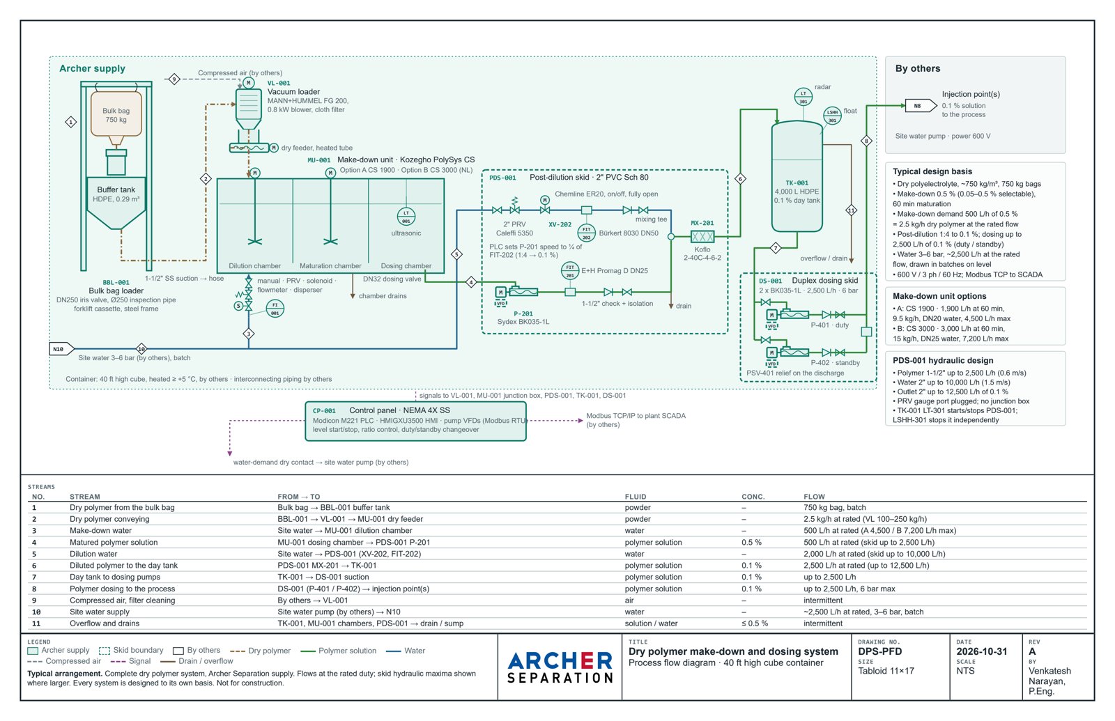
Generic flowsheet for illustration. Every Archer system is designed to its own basis; ask us for one drawn for your plant.
A polymer make-down skid we built

A compact liquid polymer make-down system from an Archer dewatering project: neat polymer metering pump, dilution water train with solenoid and pressure regulating valves, a mixed HDPE tank for ageing, and an ultrasonic level transmitter the PLC uses to batch.
- Mixer gear motor
- Neat polymer metering pump
- Solenoid valve, dilution water
- Pressure regulating valve, dilution water
- Ultrasonic level transmitter
- HDPE mixing and ageing tank with access lid
- Isolation / drain ball valves
See also the Kozegho PolySys units in 3D and our dry chemical feed and dosing system.
A complete dry polymer system in a 40 ft container
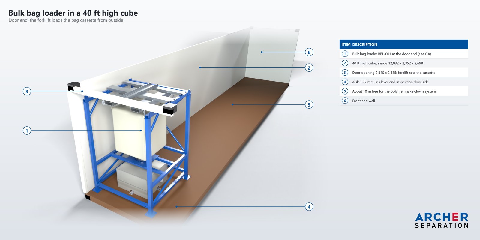
For one municipal client we designed the whole dry polymer train to fit inside a 40 ft high cube container: bulk bag in at the door, 0.1 % solution out to the injection points. Every unit was modelled in 3D, checked for clashes and for forklift and operator access, and the bag frame and tank were checked by FEA.
Bulk bag loader
A bag frame built to the container’s inside height. The forklift sets a 750 kg bag on a lift cassette from the door end; an iris valve and an inspection pipe feed a sloped HDPE buffer tank.
Make-down
A vacuum loader lifts the powder to a Kozegho PolySys CS 1900: three chambers for dilution, maturation and dosing, about 1,900 L/h at 60 min maturation.
Post-dilution
A post-dilution skid takes the 0.5 % solution down to 0.1 % with metered water, magnetic flowmeters and a static mixer, into a 4,000 L day tank.
Dosing
A duplex progressive cavity dosing skid, duty and standby, delivers up to 2,500 L/h of 0.1 % solution, paced by the plant through the control panel.
Buffer tank
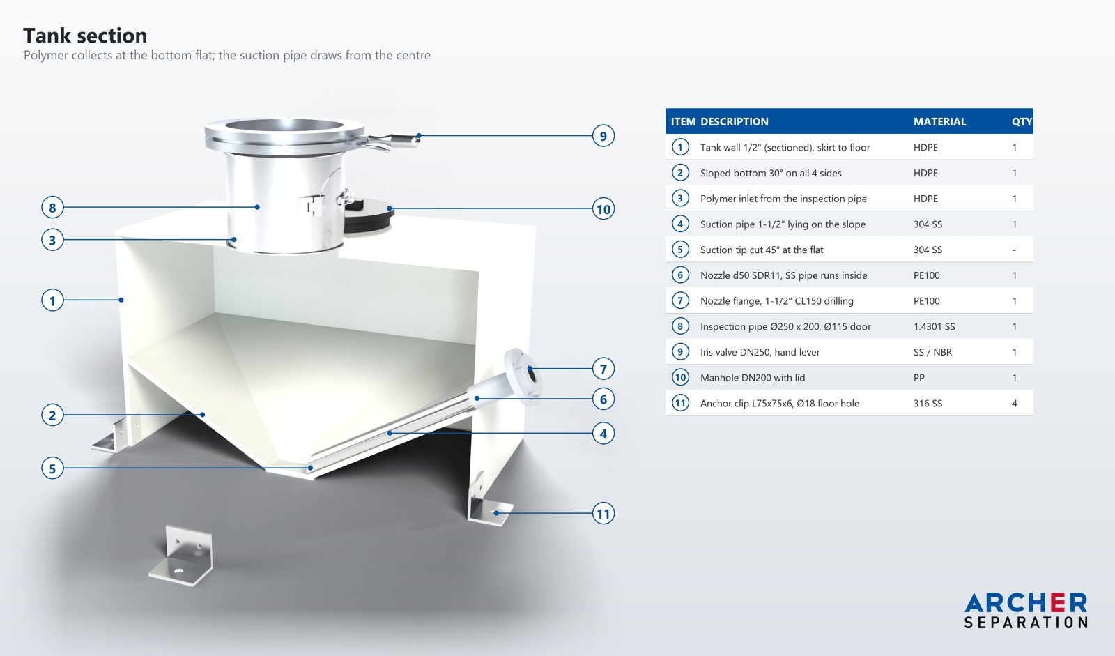
The powder collects on a sloped bottom and the vacuum loader draws it from the centre, so the bag empties fully.

PolySys CS 1900 make-down
Dry feeder, wetting cone and three agitated chambers in one HDPE tank.

Post-dilution skid
Polymer pump, dilution water with pressure reducing valve and flowmeter, mixing tee and static mixer on one frame.

Duplex dosing skid
Two progressive cavity pumps with relief valves and isolation, duty and standby.
Bulk bag loader details
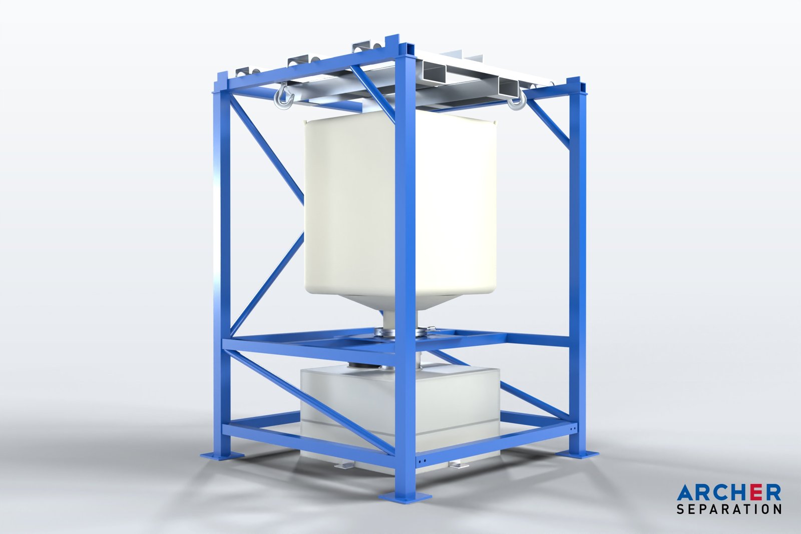
Short-headroom frame
The frame is built to the inside height of a high cube container; the bag is set on a lift cassette by forklift.
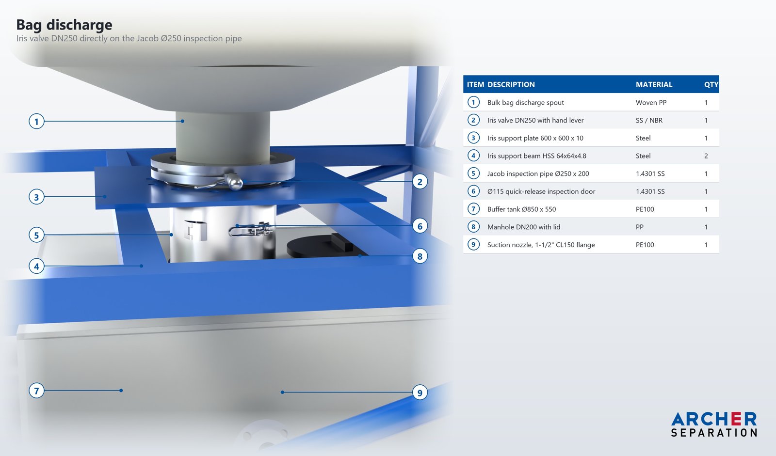
Iris valve discharge
The bag spout sits on a DN250 iris valve with a hand lever, so a part-used bag can be closed off cleanly.
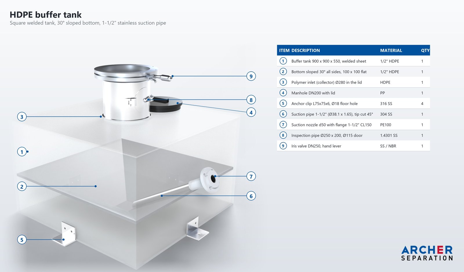
Vacuum suction wand
A stainless suction wand on the sloped bottom of the HDPE buffer tank feeds the vacuum loader.
In service: two dry polymer systems at a large wastewater plant
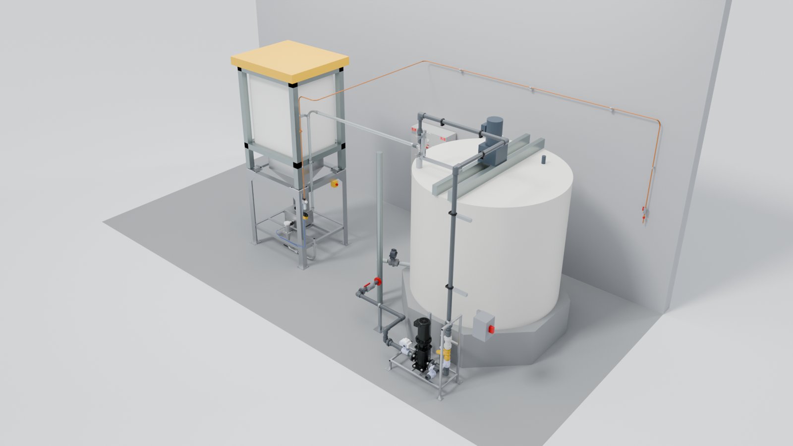
At a large regional wastewater treatment plant in the Lower Mainland of BC, Archer supplied a dry polymer make-down system for DAF thickening in 2019 and upgraded the centrifuge polymer feed in 2025–26: bulk bag unloading, volumetric screw feeding, wetting and eduction, mixing and ageing, and booster pumping.
Features
Electrical panel
All Siemens inside, with a synoptic board and bicolour LED indication of the main components, an emergency stop button, and a Siemens S7-1200 PLC for command and control with a 4″ colour display.
Mixers
Standard in the dilution and maturation chambers: 150 rpm motor drive, quick-release coupling, and shaft and 45° flat four-blade propellers in 316 SS.
Dry feeder
Solid centre-screw extraction and a compact HDPE hopper. Every system has a heater on the extractor tube, a level window and a level sensor in the hopper.
Dosing pump
Solenoid diaphragm pump controlled by pulses, or a peristaltic pump with high suction head for standard and viscous liquids, motor-driven and speed-controlled by an inverter.
Powder in 3 Chambers (Specifications)

Prepares polymer solution from powder. The dry feeder meters the powder into the first chamber, and the solution then passes through the following chambers to mix and mature before it is dosed.
Emulsion in 2 Chambers (Specifications)
A compact two-chamber unit that prepares solution from liquid emulsion polymer.

Bivalent in 3 Chambers (Specifications)

A three-chamber unit that works with either powder or liquid emulsion polymer, so you can change polymer type without changing the system.
Emulsion in 3 Chambers (Specifications)
A three-chamber unit for liquid emulsion polymer, giving the solution more time to mature before dosing.

Polyne in-line liquid polymer systems
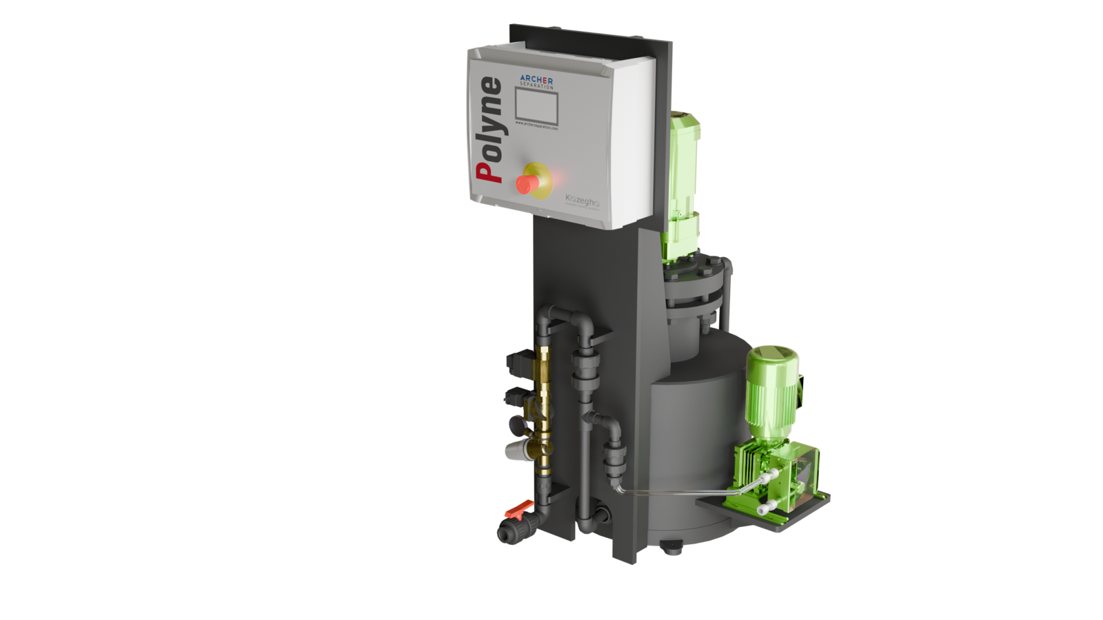
Kozegho’s Polyne units dilute liquid polymer with water in-line, as a complete skid: every component is connected and tested, so electrical and hydraulic installation is quick.
- HDPE cylindrical mixing chamber, pressurized to 1 bar to shorten residence time
- Adjustable concentration, up to about 1% solution
- Peristaltic raw polymer pump with variable speed drive
- Siemens components and a touchscreen panel; configurable process and fault alarms
- Second dilution line with pressure regulating valve, solenoid valve and water flowmeter
- Two sizes: Polyne 40 and Polyne 100
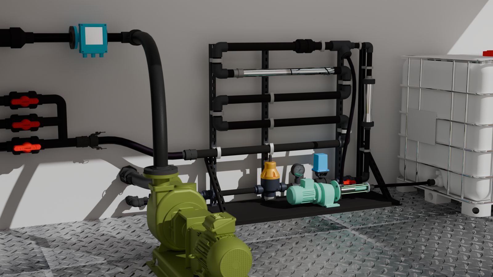
Polymer systems are also built into our containerized centrifuge systems and skid systems, piped to the static mixer ahead of the decanter.
Kozegho Polymer System
Kozegho Dosing System
Related pages
- Mining tailings and process water
- Case study: Lower Mainland WWTP dry polymer make-down systems
- Kozegho Dosing Systems
- Chemical Systems
- Decanter Centrifuges
- DAF / Dissolved Air Flotation Systems
- JarLab: jar test and lab records
Contact our team today to learn how our polymer systems can improve your processes. We also offer polymer testing and selection.
Closed-loop polymer dosing: TSS polymer control for centrifuges and DAF, and the IIoT Gateway dosing controller.