
FRP Lamella Separators
Counter-current (down-flow) lamella plate separators for oil/water and solids separation, built in FRP for hot, corrosive service.
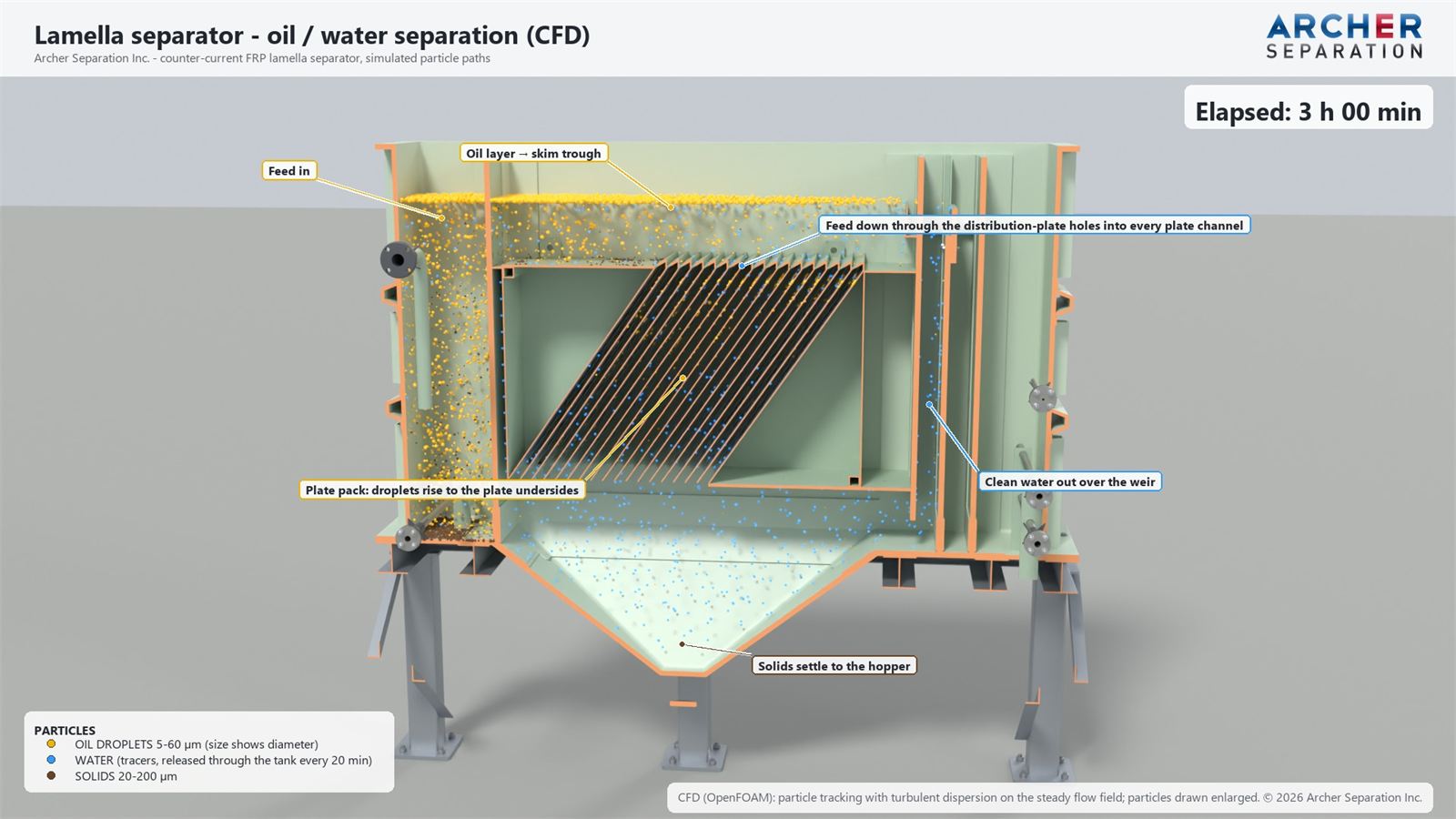
How a lamella separator works
Distribute
An inclined distribution plate with metered holes sends the feed down evenly into every plate channel.
Typical process flowOily wastewater: lamella separator, DAF and decanter Generic flowsheet for illustration. Every Archer system is designed to its own basis; ask us for one drawn for your plant.
Separate
Oil droplets rise to the plate undersides and climb against the flow to the oil layer.
Skim and settle
Oil leaves through a skim trough; solids settle to the hopper.
Discharge
Clean water leaves over an adjustable weir; the interface level is monitored.
See it working before it is built
Before any FRP is laid up, we model the separator with computational fluid dynamics (CFD). The model follows oil droplets, water and solids through the vessel, so we can see where the feed goes, whether every plate channel does its share of the work, and where oil and solids collect.
Several inlet and outlet arrangements are compared in the model before one is chosen, so changes are made on screen, where they cost hours, instead of in a finished FRP vessel.
Structure checked by FEA
The FRP vessel and its steel support frame are checked by finite element analysis for every load case: operating, flooded to the rim, maintenance drain, lifting and seismic, including sloshing.
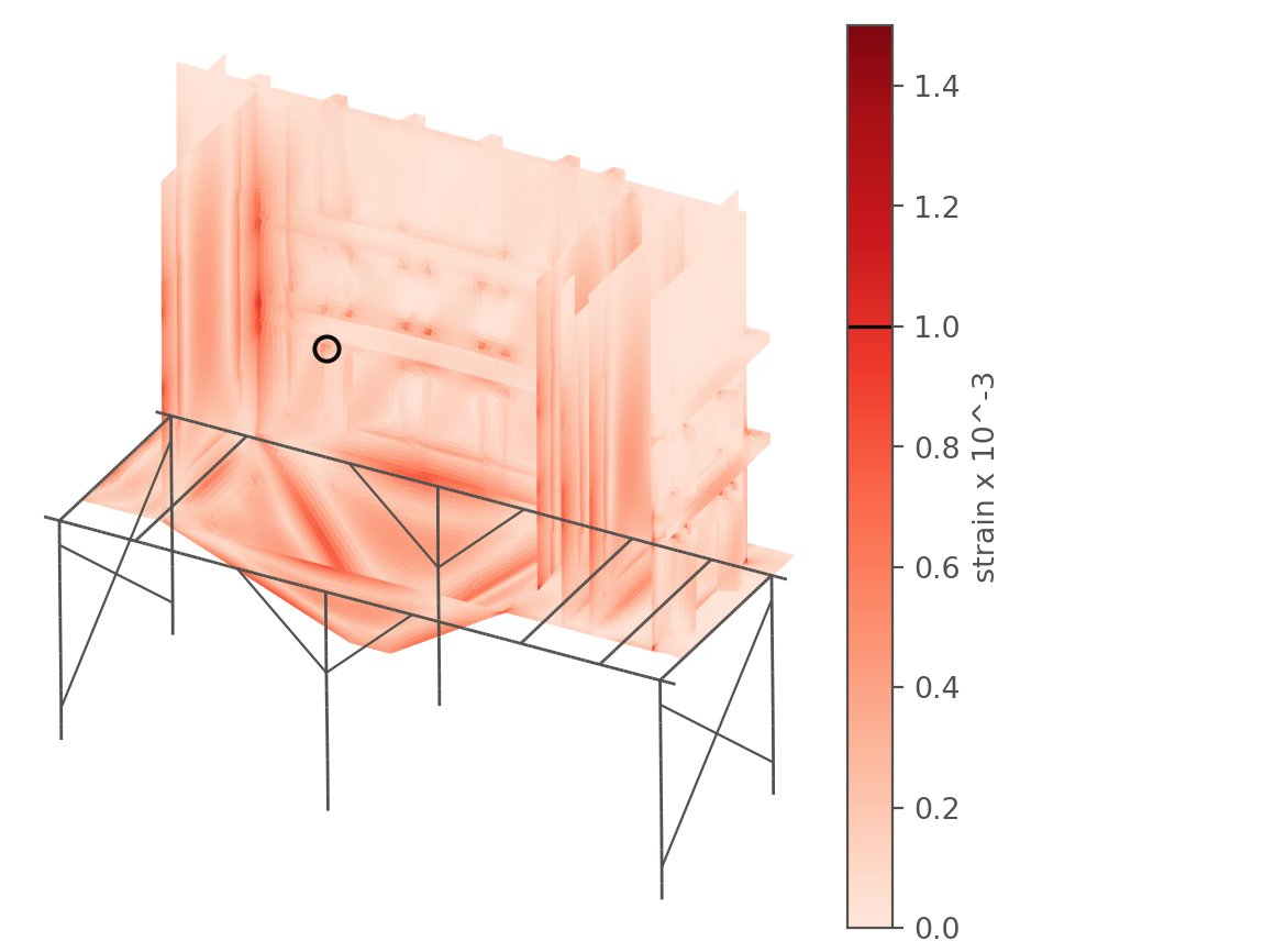
Proven before the first layer of FRP
- Plate pack sized for a target droplet cut size
- Vessel structure checked to ASME RTP-1 with finite element analysis
- Seismic sloshing loads to ASCE 7 / ACI 350.3
- CFD (OpenFOAM) with particle tracking to verify flow split and separation
- Clean-in-place spray provisions, duplex feed strainer, skid packaging
Applications
Oily wastewater
Fats, oils and grease from food processing, ahead of DAF or discharge.
Acid-oil and fat recovery
Recover oil by gravity after acid splitting, in FRP that handles the chemistry.
Solids clarification
Compact settling area for high-solids streams.
Hot, corrosive service
FRP construction for low pH and elevated temperature.
Related applications: Oil Sludge Recovery · Mining Tailings