
Containerized Centrifuge Systems for Sludge Processing / Dewatering
A complete sludge dewatering plant in a shipping container, fully piped and wired. Buy or rent.
Archer offers a complete sludge processing solution with our custom containerized centrifuges. Each unit includes essential components such as pumps, polymer systems, flow meters, and static mixers, all designed for efficient sludge management. Built in-house, these containerized systems undergo rigorous Finite Element Analysis (FEA) to ensure durability, reliability, and extended trouble-free operation.
Choose your container

| 20 ft, DDE 2342 | About 2.5 m³/h, 160–200 kg DS/h (reference unit) |
|---|---|
| 20 ft, DDE 4042 | 12–20 m³/h, up to 800 kg DS/h; insulated and heated |
| 40 ft HC, DDE 4042 | 20 m³/h at 3 % TS |
| 40 ft HC, DDE 5342 | 20–40 m³/h or more (rental and demonstration unit) |
| 40 ft + 20 ft, DDE 5342 | Up to 50 m³/h |
Capacity depends on sludge characteristics; we confirm it with your sludge before you buy or rent.
Our rental and demonstration unit
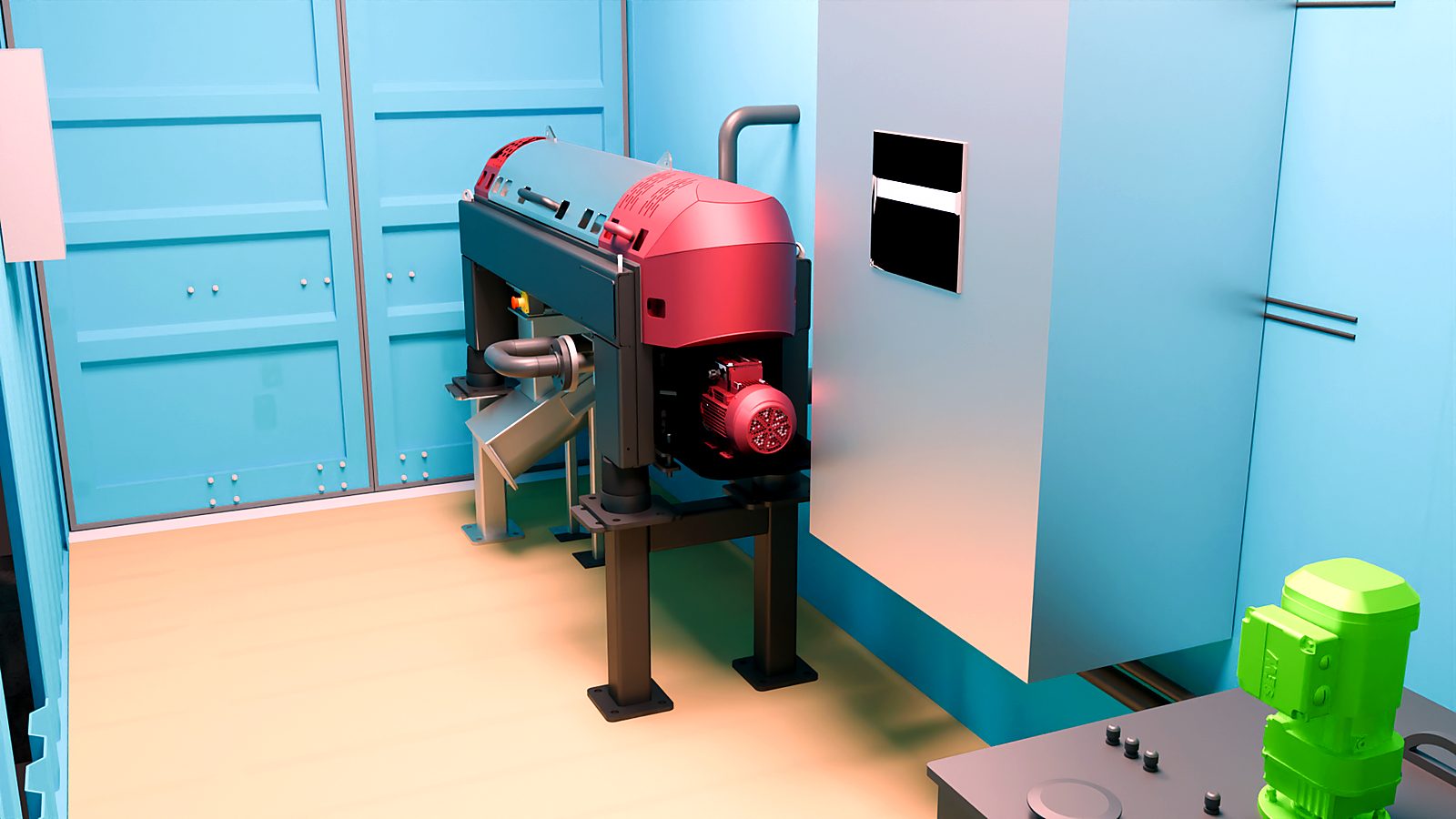
Our rental and demonstration container unit features a NEMA 12 control panel, an Archer-designed inline polymer system with a venturi eductor for rapid, efficient polymer wetting, and a custom-engineered static mixer for precise sludge and polymer blending.
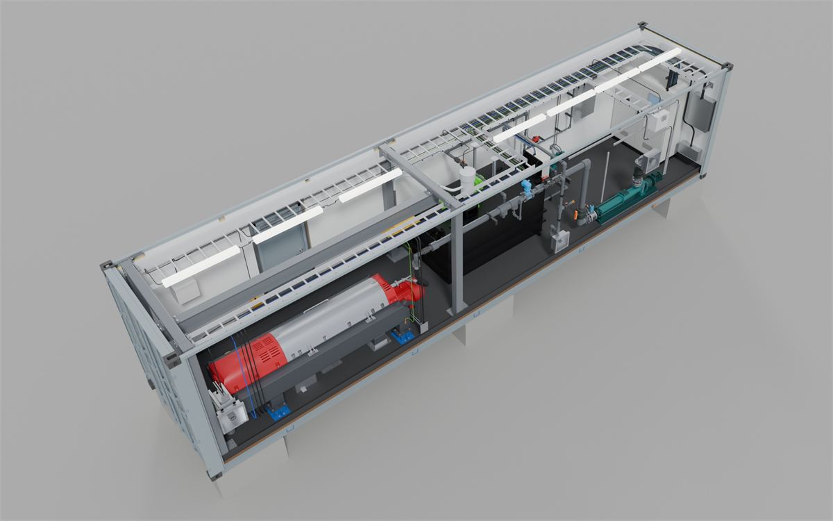
This 40-foot high-cube container has fully opening doors on the 40-foot side for ease of operation, and a removable roof for straightforward centrifuge maintenance.
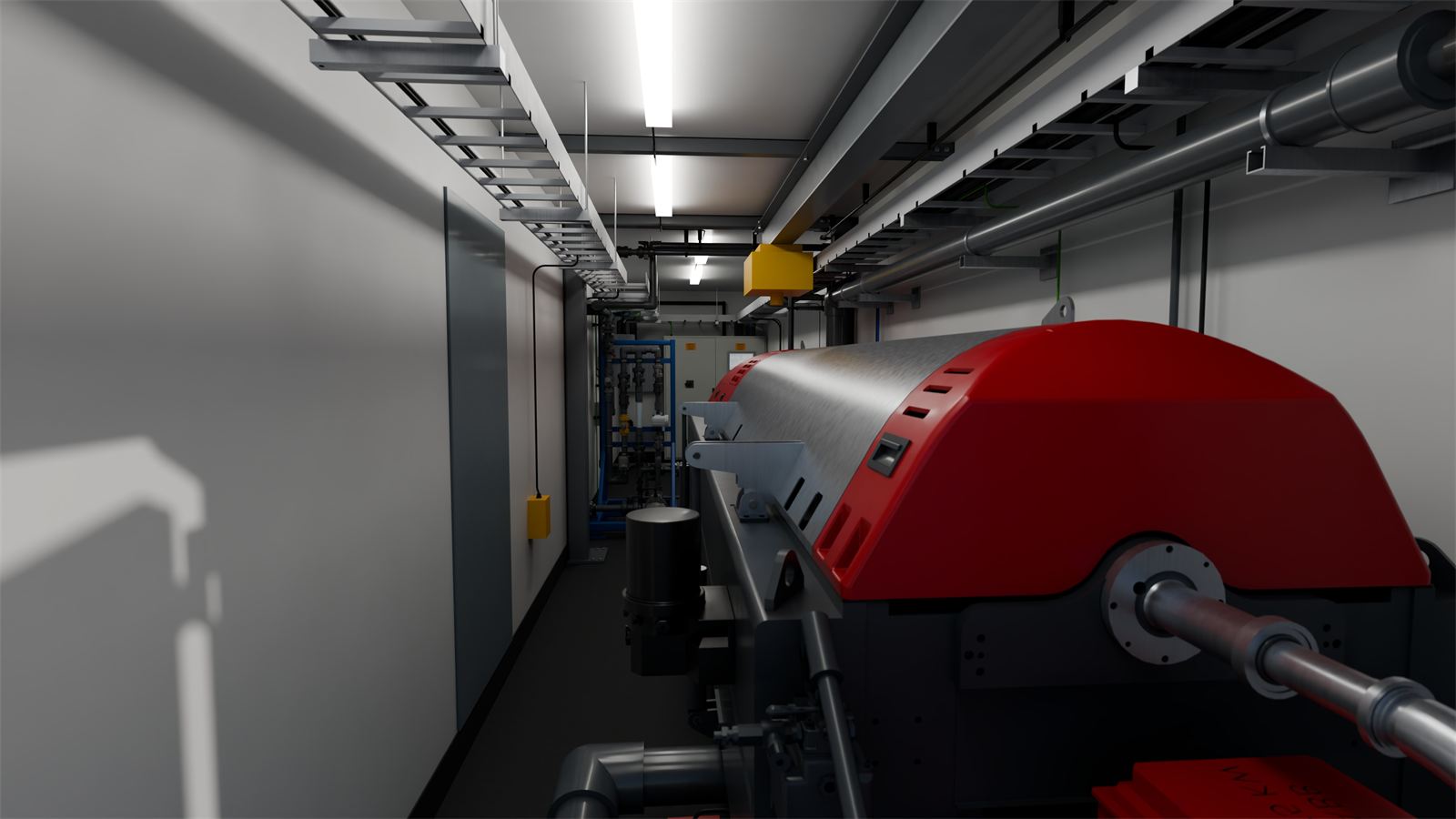
The system is equipped with dual screw conveyors: a long, swiveling conveyor that extends outside the container to discharge dewatered sludge into an adjacent bin, which can be retracted for compact storage.
Fitted with a HAUS DDE 5342 centrifuge, this container processes 20-40 m3/h or more, depending on sludge characteristics. We also offer 20-foot containers with smaller centrifuges, insulated walls, and heating for enhanced versatility.
What is inside the container
Every Archer container carries the full dewatering train, so the site only connects sludge, water and power. A progressive cavity pump draws sludge from the lagoon, digester or tank. A flowmeter paces the polymer, which our inline system makes down from emulsion and injects ahead of a static mixer. The HAUS decanter separates cake and centrate. A swivel conveyor carries the cake through the door into a bin, and the centrate returns to the plant. All hoses connect at recessed wall boxes, and the control panel reports to our IIoT gateway for remote monitoring.
Generic flowsheet for illustration. Every Archer system is designed to its own basis; ask us for one drawn for your plant.
Walk through the 40 ft unit
Walk through the 40 ft + 20 ft DDE 5342 unit
A compact 20 ft unit
Engineered with FEA and CFD
A decanter in a steel box is a dynamic load on a light floor. We check every container and skid by analysis before it is built, not after it is on site.
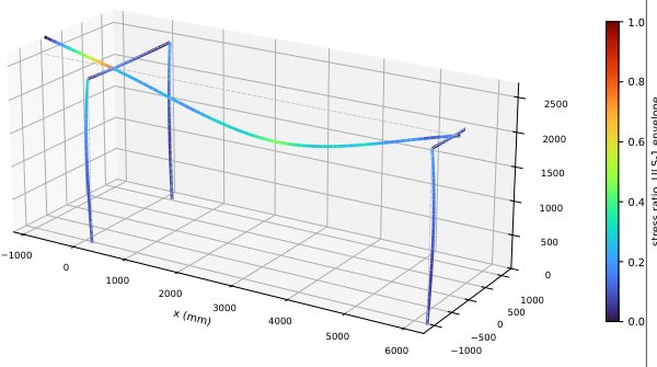
Finite element analysis (FEA)
Container floors, decanter supports, runway beams and portal frames are modelled and checked for the machine’s operating and lifting loads at every hoist position, together with lifting, transport and seismic anchorage of the loaded container or skid.
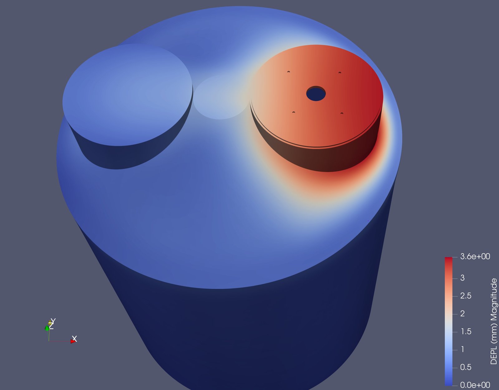
Tanks, lids and frames
The same approach covers polymer and chemical tanks, mixer mountings and skid frames, so deflection and stress are known before the first weld.
- Open, auditable analysis: code-based member and connection checks, with the plots and results in the design file
- Computational fluid dynamics (CFD) where flow decides performance: feed distribution, mixing and separation (see our lamella separator CFD)
- Clash checks on the full 3D model: every pipe, cable tray and hoist path inside the container
How we engineer
Our engineering is done in-house by Archer engineers, so the people who design your system are the people who support it. We use the same proven tools on every project, from the first layout to the final drawings:
- Electrical design, schematics and panel layouts in EPLAN
- 3D models and equipment layouts in SolidWorks
- Computational fluid dynamics (CFD) in OpenFOAM
- Finite element analysis (FEA), structural and seismic anchorage, in code_aster
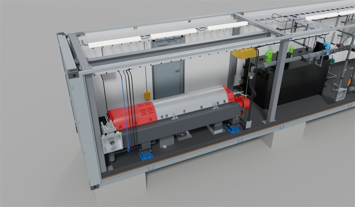
Built-in 2 t runway and hoist
Lift the rotating assembly out without bringing in a crane.
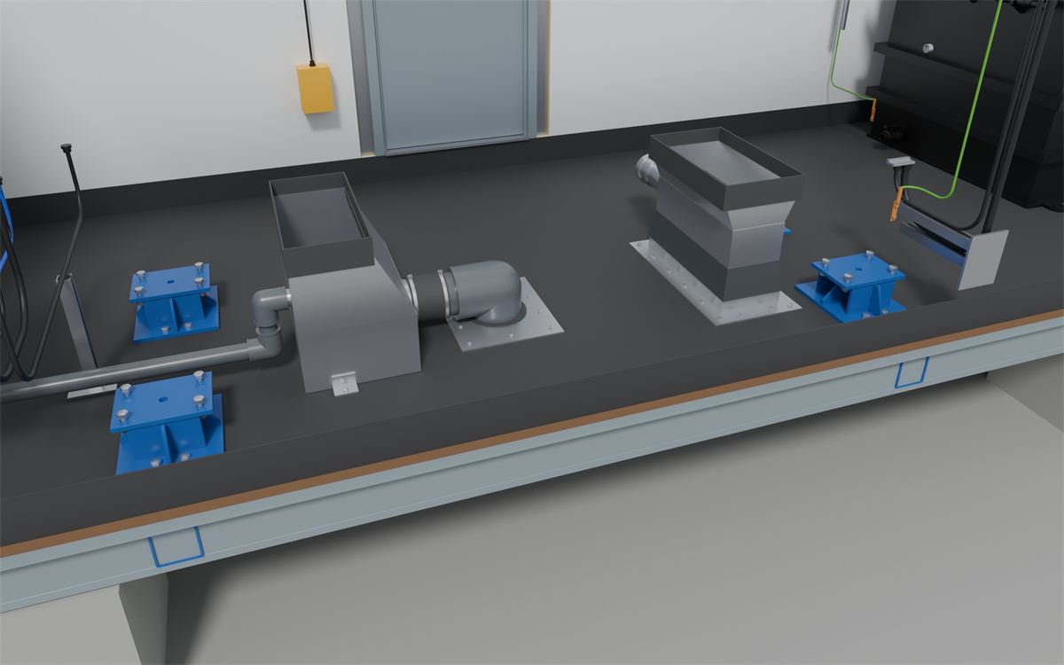
Raised container, floor discharge
Cake and centrate leave through the floor, so no conveyor passes through the wall. 6 mm polyurea floor, spill tray and hose-down.

Polymer on board
Powder or liquid polymer make-down, with optional inline TSS polymer optimization.
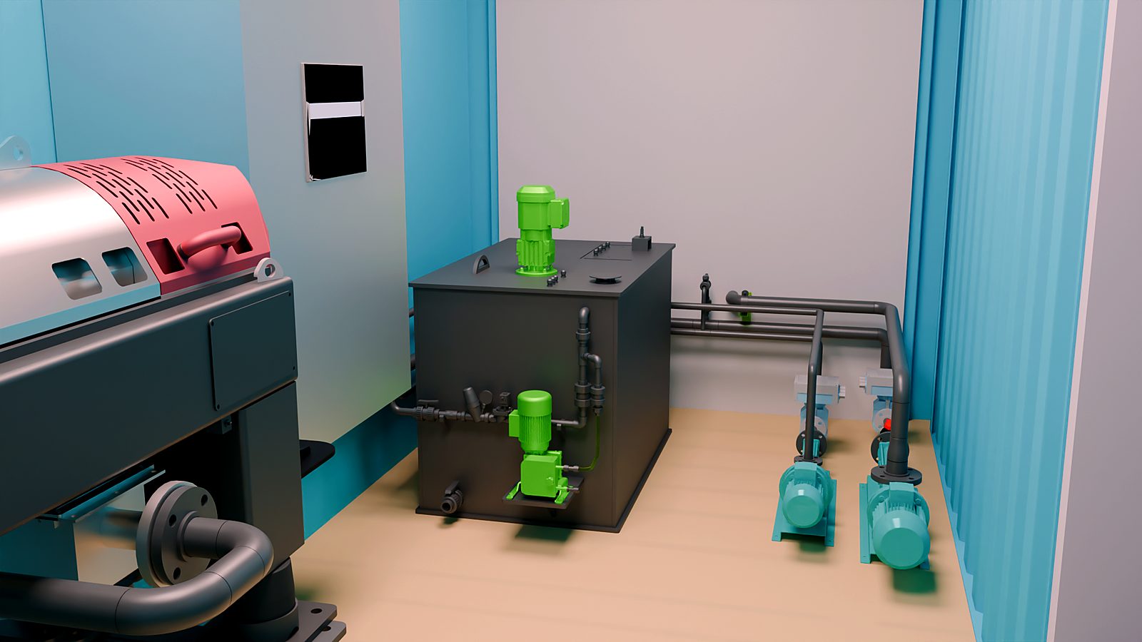
Compact 20 ft layout
Decanter, polymer system and feed pumps fit a standard 20 ft container for smaller flows.
Ready for winter, wash-down and inspection
- CSA-A277 approved, insulated, Class A washable lining
- Heater, exhaust fan and foul-air extraction from the centrifuge casing
- LED lighting and H2S detection
- Designed in-house, built in BC under Archer supervision
- PLC programming, remote monitoring and support from Port Coquitlam
Generic flowsheet for illustration. Every Archer system is designed to its own basis.
Contact us to learn more about these units and how we can help with your separation or dewatering needs!
Related applications: Oil Sludge Recovery · Mining Tailings